

Low Visibility Operations Masterclass | Part 3
A Guide on the Instrument Landing System (ILS)

Hey everyone and welcome back to this A320 Knowledge Masterclass.
The Instrument Landing System (ILS) is one of the most critical systems in modern aviation, providing precise guidance to aircraft during approaches and landings, especially in low-visibility conditions such as fog, rain, or snow. This ground-based system relies on radio signals that guide the aircraft both laterally and vertically, ensuring that pilots can make safe, accurate landings even when they can't see the runway clearly. In this article, we'll take a deep dive into the mechanics of ILS, how it works, and the key operational details pilots need to understand to use it safely.
Let’s dive right in.
Insights at a Glance:
How ILS Works: Learn about the two main components of the system—localizer and glide slope—and how they provide precise guidance to aircraft.
False Signals & Safety Risks: Understand the potential for false glide slope signals and how pilots can avoid dangerous descents.
ILS Critical & Sensitive Areas: Discover the zones around ILS antennas where aircraft and vehicles must stay clear to maintain signal integrity.
Operational Procedures: Gain insights into how air traffic control manages ILS operations, particularly in low-visibility situations.
Subscribe to the A320 Knowledge YouTube Channel!
What Is the Instrument Landing System (ILS)?
The Instrument Landing System (ILS) is a sophisticated navigation aid that ensures aircraft stay on the correct approach path during their final descent to the runway, especially when weather conditions severely limit visibility. Whether it's dense fog, heavy rain, or snow, the ILS provides precise lateral (side-to-side) and vertical (up-and-down) guidance, allowing pilots to land safely even in conditions where they might not be able to see the runway until the last moment.
The system relies on two main components: the localizer for lateral guidance, and the glide slope for vertical guidance. Both work together to ensure that the aircraft stays on the correct path and descends at the right angle, even in low visibility.
The Localizer: Lateral Navigation
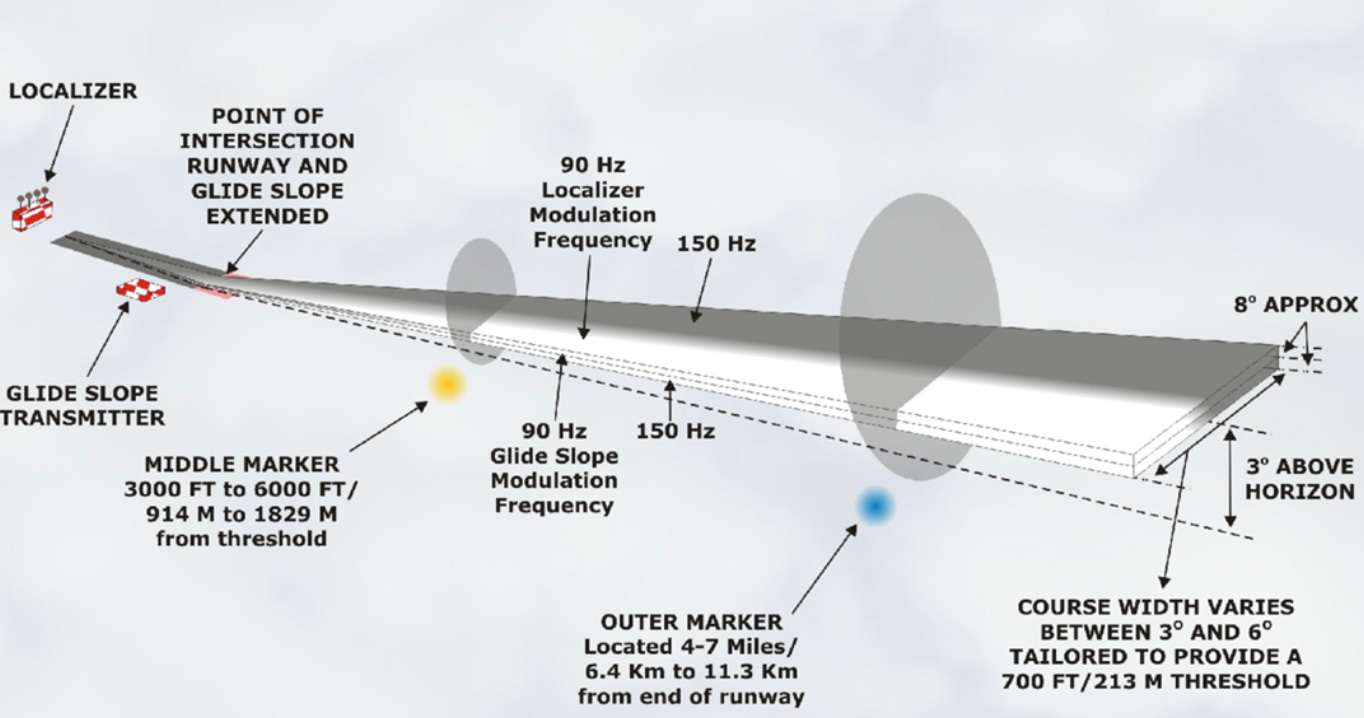
The localizer provides lateral navigation by guiding the aircraft along the centerline of the runway. This part of the system works by emitting two radio signals—one modulated at 90 Hz and the other at 150 Hz—from a ground-based antenna array usually located at the far end of the runway. These two signals are transmitted from closely spaced antennas, each producing a narrow beam. One beam is slightly directed to the left of the runway’s centerline, while the other is directed slightly to the right.
As the aircraft moves closer to the runway, its localizer receiver compares the strength of these two signals. When both signals are received at equal strength, the aircraft is aligned with the runway centerline. If the signals become uneven, it indicates that the aircraft is off-center, and the pilot can make the necessary corrections.
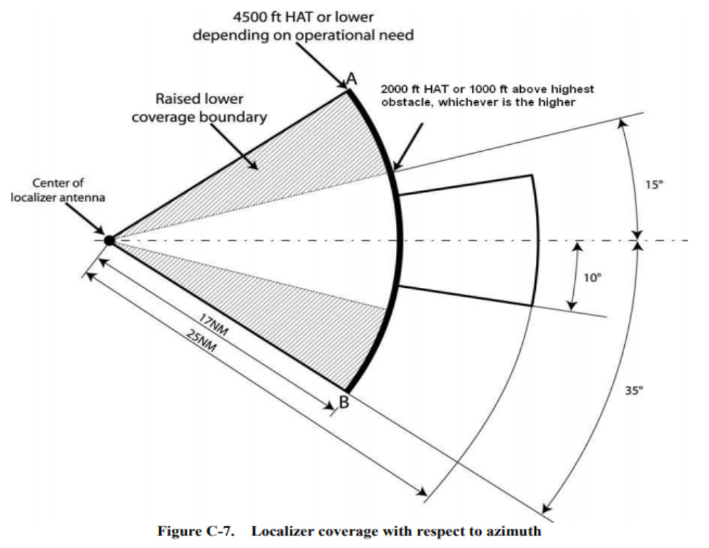
A typical localizer provides coverage up to 25 nautical miles within 10° of the runway centerline. This range gradually diminishes as the aircraft moves further from the centerline. Extended-range systems, mainly used in the United States and Canada, can offer greater coverage.
The Glide Slope: Vertical Navigation
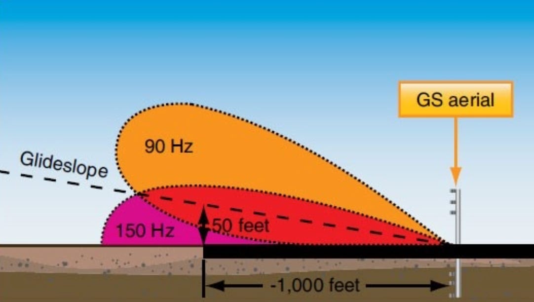
The glide slope is a critical component of the Instrument Landing System (ILS) that provides vertical guidance to aircraft during the approach phase. While the localizer ensures the aircraft remains aligned with the runway laterally, the glide slope controls the vertical aspect of the approach, helping to maintain a safe descent angle. The correct glide slope ensures that the aircraft descends at an optimal rate—neither too steep nor too shallow—avoiding the potential dangers of both excessive altitude loss or delayed landing.
The glide slope works by transmitting two distinct radio signals along the aircraft’s approach path. These signals are designed to create a precise vertical path that guides the aircraft to the runway. In a typical ILS setup, the glide slope angle is set at around 3°, which is considered ideal for most commercial aircraft. This angle ensures that the descent is smooth, efficient, and safe for landing. However, the glide slope angle can be adjusted slightly depending on the specific requirements of an airport or the terrain surrounding it.
When the aircraft is on the correct glide slope, it will descend steadily along the predetermined path. The signals from the glide slope transmitter are designed to keep the aircraft on course, preventing too sharp of a descent or an approach that might take too long. Pilots must remain vigilant during this phase, ensuring they follow the signals to safely reach the runway at the correct angle.
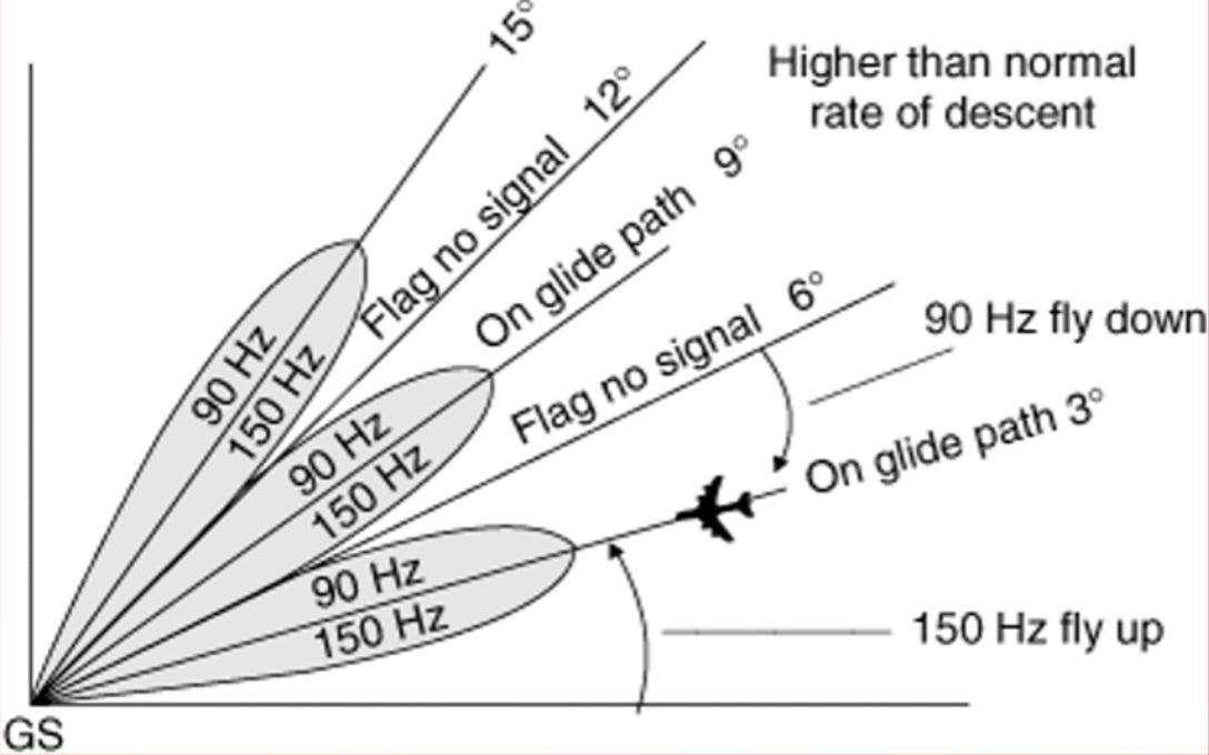
False Glide Slope Signals: The Risks and How to Prevent Errors
While the glide slope is a reliable and accurate system, false glide slope signals are a real concern and present significant safety risks during instrument approaches. These false signals can mislead the aircraft into descending along an incorrect path. For example, a false glide slope with a steeper angle, such as 9°, could cause the aircraft to descend too quickly, potentially leading to dangerous situations, including the risk of a controlled flight into terrain (CFIT).
False glide slope signals are usually caused by interference, equipment malfunctions, or incorrect signal propagation. They may occur when there is an issue with the ground equipment, such as a misalignment or malfunction of the glide slope antenna or if the aircraft is outside the range of the true glide slope signal but still picks up a distorted one. In some rare cases, a false glide slope may appear above the correct approach path, leading the aircraft to mistakenly follow this erroneous signal. In such cases, pilots need to remain extra cautious, as autopilot systems may inadvertently lock onto a false glide slope, further complicating the situation.
To minimize the risk of following a false glide slope, pilots should adopt a number of precautionary measures:
Regular Cross-Checks: Pilots should continuously cross-check their altitude, airspeed, and approach plate. The approach plate provides the correct glide slope angle, and regular checks help confirm that the aircraft is descending as expected.
Monitoring the Descent Rate: By carefully monitoring the aircraft's descent rate, pilots can quickly identify if the aircraft is descending too quickly or too slowly. If there is any discrepancy, a re-evaluation of the glide slope alignment should be conducted.
Autopilot Awareness: Pilots should be mindful of the autopilot's behavior, especially when approaching low-visibility conditions. Autopilot systems may lock onto the incorrect signal if not monitored carefully.
Key takeaway: False glide slope signals can present a serious risk during the approach phase, leading to an unsafe descent. Pilots should remain vigilant by constantly cross-referencing with their approach charts, verifying descent rates, and staying aware of potential issues with the autopilot. By maintaining awareness and utilizing sound procedures, the risks posed by false glide slopes can be mitigated.
ILS Accuracy and Limitations:
1. Signal Accuracy and Range Limitations
ILS provides highly accurate lateral (1–2 degrees) and vertical (0.5–1 degree) guidance, but its range is limited. The localizer is effective within 25 nautical miles, and the glide slope typically within 10 nautical miles. Outside these ranges, the signal becomes unreliable, and pilots should remain aware of their position relative to the runway.
2. Interference from External Factors
Weather conditions like heavy rain or thunderstorms can weaken or distort ILS signals. Radio interference from nearby equipment can also degrade the signal, leading to incorrect guidance. Pilots must monitor ILS indications carefully, especially when weather is poor or there’s potential interference.
3. Multipath Error
Multipath interference happens when ILS signals reflect off buildings or terrain, leading to distorted or delayed signals. Airports try to prevent this with proper antenna placement, but pilots should remain cautious in areas with significant infrastructure or terrain features.
4. Equipment Malfunctions
ILS systems can malfunction or become miscalibrated, causing misalignment and inaccurate signals. If a malfunction is suspected, pilots should cross-check their instruments and be ready to initiate a missed approach or switch to alternative procedures.
5. Terrain and Airport Configuration
Airports in mountainous regions or with unusual runway layouts may have ILS signals affected by terrain or obstacles. Pilots should be aware of terrain information on approach charts and ensure proper spacing between parallel ILS systems at busy airports.
ILS Critical Area and Sensitive Area
To maintain the integrity of the ILS signals, strict boundaries are defined around the localizer and glide slope antennas. These areas are divided into critical and sensitive zones.
Critical Area
The ILS critical area is the most restricted zone around the antennas, where aircraft and vehicles must stay clear during ILS operations. If any object, especially a vehicle, enters this area, it could cause interference with the signals, leading to inaccurate guidance for the aircraft. To ensure the proper functioning of the ILS, these critical areas are strictly enforced.
Aircraft are considered to have crossed the ILS critical area when they pass a designated point on the taxiway where the lights change from alternating yellow and green to solid green.
Sensitive Area
Beyond the critical area lies the ILS sensitive area, which is a larger zone that still regulates the movement of aircraft and vehicles to ensure they do not interfere with the ILS signals. While not as strictly controlled as the critical area, this zone still ensures that large objects do not cause disruptions. For instance, taxiing aircraft could potentially distort the signals, so ATC may increase separation between aircraft in such areas.
Air Traffic Control and ILS Operations
Air Traffic Control (ATC) plays a crucial role in managing ILS operations, particularly during periods of low visibility. ATC is responsible for ensuring that aircraft and vehicles stay clear of the ILS critical and sensitive areas to prevent interference with the signals. In situations where visibility is reduced, ATC may also increase the separation between aircraft to ensure that the ILS signals remain stable.
In addition to managing these restricted areas, ATC works closely with pilots to ensure that the ILS system is functioning properly. For example, if a vehicle or aircraft inadvertently enters the ILS sensitive area, ATC may request a separation from other aircraft, even if the weather does not require low-visibility procedures.
Pilots also have a responsibility to ensure the stability of the ILS signals. When operating in low-visibility conditions, pilots should request additional separation from other aircraft if they believe it will help ensure the accuracy of the ILS signals.
Key takeaway: ATC and pilots work in tandem to maintain the integrity of ILS operations and ensure safe landings, especially when visibility is compromised.
Key Takeaways:
The localizer ensures lateral alignment with the runway, guiding the aircraft on the correct path.
The glide slope ensures a safe vertical descent, but false glide slopes can cause dangerous conditions if not monitored.
ILS critical and sensitive areas protect the integrity of the ILS signals, and pilots must ensure they avoid interference by staying clear of these zones.
Air Traffic Control and pilots work together to ensure the ILS operates smoothly, with extra precautions taken during low-visibility situations.
If you found this Masterclass helpful, consider sharing it with others or leaving a comment below with your thoughts.
I’ll see you in the next one.
A320 Knowledge